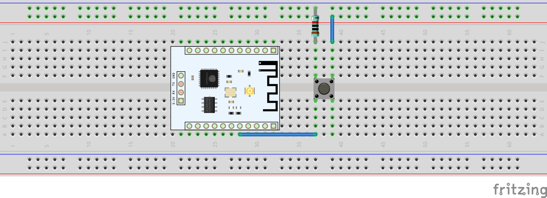
Assemble
The Connected to column in the following table makes a few assumptions on orientations. Refer to the module orientation page for details.
| ESP32 Pin |
Connected to |
Module |
| 21 |
0 |
pin pad |
| 22 |
2 |
pin pad |
| 23 |
3 |
pin pad |
| 25 |
4 |
pin pad |
| 12 |
5 |
pin pad |
| 13 |
6 |
pin pad |
| 14 |
7 |
pin pad |
| 15 |
8 |
pin pad |
| 0 |
0 |
lock relay |
| 5v |
1 |
lock relay |
| GND |
2 |
lock relay |
| GND |
0 |
PIR Sensor |
| 33 |
1 |
PIR Sensor |
| 5V |
2 |
PIR Sensor |
| 19 |
RX |
CH559 USB Host |
| 18 |
TX |
CH559 USB Host |
| 5V |
5V |
CH559 USB Host |
| GND |
GND |
CH559 USB Host |
| 32 |
0 |
Hard Reset Button |
Solenoid Lock to RC Battery Connection Table
| Solenoid Lock |
Connected to |
Module |
| Positive (red) |
NO |
lock relay |
| Negative (black) |
Negative (black) |
12V 2000 mAh RC Battery |
| Lock Relay |
Connected to |
Module |
| NO |
Positive (red) |
Solenoid Lock |
| COM |
Positive (red) |
12V 2000 mAh RC Battery |
| Button |
Connected to |
Module |
|
32 |
ESP32 |
Pin Orientation
video coming soon
